Rangking Universitas versi Webometrics Januari 2008
Wednesday, January 30, 2008
Januari, 28 2008. Hari yang tunggu oleh beberapa Perguruan Tinggi dengan dikeluarkan suatu peringkat Perguruan Tinggi oleh Webometrics. Di ruang kerja BAPSI - UG saat pagi dari jam 9 lewat 15 menit, ada Akbar yang sedang menantikan pengumuman tersebut.
Webometrics merupakan menentukan peringkat perguruan tinggi berdasar atas keunggulan dalam publikasi elektronik (e-publication) yang terdapat dalam domain dari masing-masing perguruan tinggi. UGM dan ITB wakil universitas di Indonesia untuk menduduki Asia Top 100 versi Januari 2008, yang di release pada tanggal 29 Januari 2008. Kemana kampusku Gunadarma ? Ternyata masuk dalam rangking 11 dari 17 perguruan tinggi se-Indonesia dan untuk kategori rangking dunia (World Ranking) Gunadarma mendapatkan rangking ke-3738 mengalahkan PENS-ITS, Binus,Unpar, Unpad dan Unila di Top 5000. Bagaimana penentuan rangking tersebut ? Untuk mengukur keunggulan tersebut, Webometrics menggunakan 4 indikator, yakni :
Size (s) yaitu jumlah halaman publikasi elektronik yang terdapat dalam domain web PT
Vizibility (v) atau jumlah halaman lain yang mencantumkan URL domain PT yang dinilai
Rich Files (rf) yaitu relevansi sumber elektronik dengan kegiatan akademik dan publikasi PT tersebut
Scholar (sc) yaitu jumlah publikasi dan sitasi bermutu pada domain PT.
Data yang dikumpulkan dengan 4 indikator tersebut diolah dan digunakan untuk memeringkat kurang lebih 5.000 PT dari seluruh dunia. Daftar peringkat PT itu dikeluarkan 2 kali setiap tahun, yakni bulan Januari dan Juli
Rangking PT = (4xV) + (2xS) + (1xR) + (1xSc)
Formula rangking ini telah direvisi sejak Januari 2008 menjadi seperti di bawah (updated: 1 pebruari 2008) - [by Romi Satrio Wahono]:
Penasaran Perguruan Tinggi anda masuk tidak 17 dari 5.000 PT se-dunia ? Silahkan lihat dibawah atau tidak percaya klik disini ;
World Ranking
University
Size
Visibility
Rich Files
Scholar
734
GADJAH MADA UNIVERSITY
692
1,449
1,010
789
844
INSTITUTE OF TECHNOLOGY BANDUNG
1,033
1,446
371
978
1998
UNIVERSITY OF INDONESIA
1,351
4,106
4,901
1,723
2472
BRAWIJAYA UNIVERSITY
2,326
6,202
1,811
2,786
2546
BOGOR AGRICULTURAL UNIVERSITY
3,575
4,098
978
2,287
2841
PETRA CHRISTIAN UNIVERSITY
4,431
3,412
582
2,433
2981
INSTITUT TEKNOLOGI SEPULUH NOPEMBER
3,400
3,809
4,739
2,448
3297
HASANUDDIN UNIVERSITY
3,669
3,536
3,834
4,221
3356
SEKOLAH TINGGI TEKNOLOGI TELKOM
3,703
3,770
5,079
3,234
3544
AIRLANGGA UNIVERSITY
5,537
5,160
557
1,872
3738
GUNADARMA UNIVERSITY
5,829
1,026
3,484
3,005
3778
ELECTRONIC ENGINEERING POLYTECHNIC INSTITUTE OF SURABAYA
5,461
3,266
2,052
3,480
3803
BINA NUSANTARA UNIVERSITY
3,791
4,318
6,350
3,760
4716
PARAHYANGAN CATHOLIC UNIVERSITY
6,106
4,410
4,437
3,369
4747
DUTA WACANA CHRISTIAN UNIVERSITY
4,573
5,966
8,246
3,323
4786
UNIVERSITAS PADJADJARAN
4,510
7,028
6,998
3,798
4982
LAMPUNG UNIVERSITY
5,682
4,821
6,350
3,800
UG Kapan bisa masuk 100 Top World ? Bulan juli penentuan apakah bisa bertahan atau tidak. Bisa menaikkan peringkat dan jangan sampai turun atau jangan sampai di kalahkan oleh perguruan tinggi yang sekarang masih di bawah.
Introduction to Gears No good robot can ever be built without gears. As such, a good understanding of how gears affect parameters such as torque and velocity are very important. In this tutorial I will first talk about the basics of gears, how to use them properly along with simple equations, and then I will go into specific types of gears.
Mechanical Advantage, Torque vs. Rotational Velocity Gears work on the principle of mechanical advantage. This means that by using different gear diameters, you can exchange between rotational (or translation) velocity and torque.
As with all motors, by looking at the motor datasheet you can determine the output velocity and torque of your motor. But unfortunately for robots, motors commercially available do not normally have a desirable speed to torque ratio (the main exception being servos and high torque motors with built in gearboxes). For example, do you really want your robot wheels to rotate at 10,000 rpm at low torques? In robotics, torque is better than speed.
With gears, you will exchange the high velocity with a better torque. This exchange happens with a very simple equation that you can calculate:
Torque_Old and Velocity_Old can be found simply by looking up the datasheet of your motor. Then what you need to do is put a desired torque or velocity on the right hand side of the equation. My statics and dynamics tutorials can help you decide on a reasonable torque and/or velocity for your robot.
So for example, suppose your motor outputs 3 lb-in torque at 2000rps according to the datasheet, but you only want 300rps. This is what your equation will look like:
3 lb-in * 2000rps = Torque_New * 300rps
With highschool algebra you can then determine that your new torque will be 20 lb-in.
Now suppose, with the same motor, you need 5 lb-in (minimum force to crush a cat, obviously). But suppose you also need 1500rps minimum velocity. How would you know if the motor is up to spec and can do this? Easy . . .
3 lb-in * 2000rps = 5 lb-in * Velocity_New
Velocity_New = 1200rps
You now have just determined that at 1200 rps the selected motor is not up to spec. Using the simple equation, you have just saved yourself tons of money on a motor that would have never worked. Designing your robot, and doing all the necessary equations beforehand, will always save you tons of money and time.
Gearing Ratios I have done the equations, but how do you mechanically swap torque and velocity? You would use two gears (sometimes more) of different diameters to have a particular gearing ratio. In any pair of gears, the larger gear will move more slowly than the smaller gear, but it will move with more torque. Thus, the bigger the size difference (or gearing ratio) between two gears, the greater the difference in speed and torque.
The gearing ratio is the value at which you change your velocity and torque. Again, it has a very simple equation. The gearing ratio is just a fraction which you multiple your velocity and torque by.
Suppose your gearing ratio is 3/1. This would mean you would multiple your torque by 3 and your velocity by the inverse, or 1/3.
Achieving a Particular Gearing Ratio If you wanted a simple gearing ratio of say 2 to 1, you would use two gears, one being twice as big as the other. It isn't really the size as much as the diameter ratio of the two gears. If the diameter of one gear is 3 times bigger than the other gear, you would get a 3/1 (or 1/3) gearing ratio. You can easily figure out the ratio by hand measuring the diameter of the gears you are using.
For a much more accurate way to calculate the gearing ratio, calculate the ratio of teeth on the gears. If one gear has 28 teeth and the other has 13, you would have a (28/13=2.15 or 13/28=.46) 2.15 or .46 gearing ratio. I will go into this later, but this is why worm gears have such high gearing ratios. In a worm gear setup, one gear always has a single tooth, while the other has many - a guaranteed huge ratio. Counting teeth will always give you the most exact ratio.
Gear Efficiency Unfortunately, by using gears, you lower your input to output power efficiency. This is due to obvious things such as friction, misalignment of pressure angles, lubrication, gear backlash (spacing between meshed gear teeth between two gears) and angularmomentum, etc. Different gear setups, different types of gears, different gear materials, and wear and tear on the gear, will all have different efficiencies. The possible combinations are too big to list, so I will give you an estimated efficiency to expect with each gear type below. You can also find a much more exact efficiency by looking up the datasheet on the gears you are using.
For example, suppose you use two spur gears, you would typically expect efficiency to be around ~90%. To calculate, multiply that number by your Velocity_New and Torque_New to get your true output velocity and torque.
if (from above example) Gearing ratio = 2/3 Torque * 2/3 = 6.7 lb-in Velocity * 3/2 = 150rps
Direction of Gear Rotation When designing your gear setup you should understand how gearing changes the rotation direction of your output. Two gears touching will always be counter rotation, meaning if one rotates clockwise, the other will always rotate counterclockwise. Obvious, I know. But what if you have a chain of say 6 gears touching? The rule is, an odd numbers of gears always rotates in the same direction, and even numbers of gears are counter-rotational.
Gear Chains (more than 2 gears together) Suppose you have 30 gears (holy squirrels!), all in order, like in the image above. How in the monkies do you calculate the gearing ratio of that behemoth? Easy. Ignore all the gears in between the very first and very last gear. If the diameter of the first gear is 2 inches, and the diameter of the last is 1 inch, you have a 2:1 ratio. The gears in between do not matter. Now what direction does the last gear rotate? Easy, you have an even number of gears, so it is counter-rotational of the first gear. What efficiency do you have? Well thats:
Compound Gears A compound gear is where you have two gears fixed on the same shaft.
It is easy to figure out that if they are on the same shaft, the velocity (rotations per second) is the exact same. To calculate torque, you must use the moment arm balance equations from my statics tutorial. In this case, the radius is the moment arm.
simplifying, we get: torque_motor * radius_gear1 = weight * radius_gear3
so therefore the minimum required motor torque is torque_motor = weight * radius_gear3 / radius_gear1
Now what if you wanted the weight to lift at 2 feet/sec. What rotations per second and direction must the motor rotate at?
writing down the equations: rps_motor * radius_gear1 = rps_gear2 * radius_gear2 rps_gear2 = rps_gear3 rps_gear3 * 2*pi*radius_gear3 = velocity_weight
simplifying, we get: rps_motor * radius_gear1 = rps_gear3 * radius_gear2 or rps_motor * radius_gear1 = velocity_weight / (2*pi*radius_gear3) * radius_gear2
so therefore the required motor rps is rps_motor = 2 ft/sec * radius_gear2 / (2*pi*radius_gear3 * radius_gear1)
Gear Pitch When selecting your gears, the three most important numbers you must know are pitch, pitch diameter, and number of teeth.
The pitch diameter is as shown. To calculate the pitch, simply use this equation:
Pitch = # teeth / pitch circle diameter (in inches)
For example, a gear with 72 teeth and a 1.5" pitch diameter is 48 Pitch. Gears that mesh must both have the same pitch and pressure angle (usually 20 degrees).
Gear Types All gears, no matter the type, work on the same principles above. However the different types let you accomplish different things. Some types of gears have high efficiencies, or high gearing ratios, or work at different angles, for example. Below are the main common types. This is not a complete list. It is also possible to have a combination in types.
Note: The efficiencies listed are only typical. Because of many other factors could be present, the listed efficiencies should only be used as a guide. Often manufacturers will give you expected efficiencies in the datasheets for their gears. Remember, wear and lubrication will also dramatically affect gear efficiencies.
Spur gears are the most commonly used gears due to their simplicity and the fact that they have the highest possible efficiency of all gear types. Not recommend for very high loads as gear teeth can break more easily.
Helical gears operate just like spur gears, but offer smoother operation. You can also optionally operate them at an angle, too. Unfortunately, due to the complex shape, they are generally more expensive.
Two gears with a chain can be considered as three separate gears. Since there is an odd number, the rotation direction is the same. They operate basically like spur gears, but due to increased contact area there is increased friction (hence lower efficiency). Lubrication is highly recommended.
To change the length of any chain, you will need what is called a chain breaker. This is a cheap device you can buy at any bike store. It helps in removing and placing pins within the chain.
Rack and Pinion is the type of gearing found in steering systems. This gearing is great if you want to convert rotational motion into translational. Mathematically, use radius = 1 for the straight 'gear'.
Worm gears have a very high gearing ratio. To mathematically calculate, consider the worm gear as a single tooth. Another advantage to the worm gear is that it is not back-drivable. What this means is only your motor can rotate the main gear, so things like gravity or counter forces will not cause any rotation. This is good say if you have a robot arm holding something heavy, and you don't want to waste power on holding torque. The efficiency is low, but lubrication really helps.
Planetary gears have the highest commercially available gear ratios you would ever want to put on a robot. But since they are somewhat complicated, you would never need to build one, just use it. The datasheet should tell you the gearing ratio - I just wanted you to know if you need a really really high gearing ratio for a robot, planetary gears are the way to go. Even better, some planetary gears offer multiple gearing ratio's that are user configurable!
More Information If you wish for an even more in-depth tutorial about gear selection, you can find it in this advanced gear selection tutorial. I didn't write it, but it's easy to follow and understand. Where can you buy gears? Check my robot parts list and the ad window at the top right of this page for links.
Introduction to Mechanical Engineering Theory, Energy This tutorial will cover the practical applications of understanding energy with respect to robots. I do not want to lecture you on high school physics, so I will just go straight to the juicy stuff. What will make this tutorial very useful is that you can simply use the laws of physics to determine the minimal amount of energy your robot needs to perform any desired task (will help you select a battery).
A warning to those who don't like math - this tutorial has a lot of it. If you don't want to bother with the theory, feel free to simply skip to my Robot Energy Calculator.
Potential Energy Potential energy is the energy 'stored' within an object 'at rest'. For example, if you hold a rock in your hand, it has a potential energy of:
potential energy (measured in joules) = mass (kg) * gravity (m/s^2) * height (m)
Now unless your robot is a rock, this at first appears to be useless math. Now suppose your robot were to climb a cliff, how much energy will be drained from your robot battery? Well, the energy your robot would need would be equal to the potential energy at the top of the cliff.
Or suppose you had a robot helicopter and you wanted to determine the maximum altitude it can go with a particular battery. Then you would simply reorder the equation slightly and get this:
(note that this does not leave enough energy to survive the trip back down)
Kinetic Energy Kinetic energy is the amount of energy required to accelerate/decelerate a robot.
Lets say you have a typical wheeled robot running on perfectly flat zero friction loss terrain. In this scenario, there are only two drains on energy - acceleration and deceleration. Both can occur at any time, not just at stop and start locations, but also when turning and rotating.
So how do we calculate this? Simple, use the kinetic energy equation:
energy = 1/2 * mass * velocity^2
where velocity is the desired maximum velocity.
For example, lets say our 1kg robot starts at rest and accelerates to 1 m/s, rotates 90 degrees and then travels at 2 m/s, then decelerates back to zero velocity. How much energy was spent?
Simplifing the above, it starts moving, stops to rotate, moves again, and then stops again. Or:
energy = 1/2 * 1 kg * ( 1 m/s + 2 m/s)^2 * 2 = 18 Joules
Notice that I multiplied by two - this is because the robot accelerated twice and decelerated twice. The energy to start moving equals the energy to stop moving!
Unified KE/PE Now at any point in time your robot has some amount of both kinetic energy and potential energy. For simplicity, in this tutorial we will assume that horizontal motion requires kinetic energy and vertical motion requires potential energy (see below image). When summing this amount, we can then calculate how much energy your robot will require to perform any task.
For example, lets suppose our wheeled robot is driving up a hill. In other words, your robot is doing two things - going up, AND driving horizontal. If you calculate each separately, you can then sum them up for total energy required.
energy = mass * gravity * hill_height + 1/2 * mass * velocity^2 * 2
Energy Losses The above examples only occur in ideal situations. In reality your robot will lose energy from a great multitude of sources such as air friction, ground friction, gears, thermal losses, circuit resistance losses, etc.
Typically, these sources are too complex to mathematically calculate, and so we have two choices. We build mockups/prototypes to test, or we just guess based on intuition. If you are unable to create a mathematical model for your first design, you must use intuition and guesswork. If you wish to build 'new and improved' designs, then you can experiment on your previous prototype.
Since you are reading this tutorial I am assuming you do not have a good intuition when determining these energy losses so here is a quick guide:
For most robots air friction can be ignored. Only account for air friction when your robot is very large (huge surface area), shaped like a parachute (you get the idea), or has a high velocity (air friction is proportional to velocity). To otherwise mathematically model this would require CFD, or computational fluid dynamics simulations.
Ground friction losses occur as distance is traveled. If your robot was operating on say rough terrain and traveled a specific distance, your robot would need to constantly accelerate to counter the friction induced deceleration.
For example,
deceleration_ratio = # of times to re-accelerate / unit_distance energy loss from friction = deceleration_ratio * distance_traveled * kinetic_energy
A perfectly designed system in an ideal environment would yield a deceleration ratio of 0. A ratio of 1 would be realistic, and even higher would represent high friction in your system.
If your robot does not use a thermal form of energy (like a combustion engine), then you can ignore thermal losses as they would be fairly small. Calculating thermal losses (in realistic settings) is way to complex for all but the experts.
Circuit losses can be calculated: unused_power = current^2 * resistance, where resistance and current can be derived from your schematic, ohm's law, and part datasheets. With today's electronics this can be considered neglible for most robots.
Battery Energy I have been saying 'energy' for a while now, but how do you relate this number to the energy stored in your robot battery?
power (watts) = voltage * current joules = watts * seconds Battery Energy = voltage * mAh (watt hours) * 60 * 60 / 1000
For example, a 6V battery rated at 2000mAh would have 43200 joules of energy.
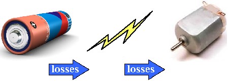
Energy Conversion (and losses from) Energy conversion is when a form of energy is changed into another form of energy. For example, your robot battery stores chemical energy. When you attach a motor to your battery, this chemical energy is converted to spin motors which then creates rotational mechanical energy.
As a robot builder, you want to have as few possible conversions as possible. Why is this? Because no conversion is 100% efficient. This is why motors get hot - thermal energy losses that provide no benefit! As a matter of fact, you can typically expect most conversions to be between 30% and 70% efficient. That's a huge loss in energy!
Let me give you a good example on this, a specific example that you should be able to relate to. And I'm apologizing now for those who think electric cars will save the world . . .
So suppose I ask you which is more efficient, an electric car or gasoline powered car? I would make the argument that a gasoline-powered car is significantly more efficient, and hence wastes much less energy. What is the basis for my argument? Well, energy conversion efficiency!
Lets start off with how to power the electric car: Coal at a power plant (chemical energy) is burned (thermal energy) to expand water vapor gas to spin a turbine (mechanical energy) which acts as a generator to create electricity (electrical energy) which is then stored in your car battery (chemical energy) and then used to power the car motors (electrical energy) to provide mechanical motion (mechanical energy).
Counting, that's 7 forms of energy with 6 conversions. Assuming each conversion is on average 70% efficient, thats:
efficiency^(conversions) = final efficiency or .7^6 = .118 = 11.8% efficient
Now for a gasoline powered car: Gasoline is stored in your car (chemical energy) and ignited in the engine (thermal energy) to expand gasses to push pistons (mechanical energy) that rotate your car wheels.
Counting again, that's 3 forms of energy with 2 conversions. Assuming each conversion is on average 70% efficient, that's:
efficiency^(conversions) = final efficiency or .7^2 = .49 = 49% efficient
I want to stress this is not proof that gasoline powered cars are lesser/greater polluters than electric cars, just that gasoline cars are significantly more efficient energy-wise. In reality, the typical conversion efficiency of a typical power plant is around 30%, with yet more losses are experienced when transporting electricity down power lines. And then there are yet more energy losses such as with trucking in gasoline/coal to various locations, etc.
So if you wanted to calculate a conversion loss for a battery-powered robot, you would do say:
90% battery to electricity 60% electricity to mechanical motion
Therefore:
Battery energy after conversion = Battery_Energy * efficiencyA * efficiencyB . . . or = Battery_Energy * .9 * .6
So to calculate loss of energy from conversion,
Battery_Energy*(1 - efficiencyA * efficiencyB) = Energy Loss
Final Equation Summing up everything you learned we can now form a general equation for calculating required energy for your robot:
Required_Energy = mass * velocity^2 + mass * gravity * height + deceleration_rate * distance traveled * (1/2 * mass * velocity^2) + Battery_Energy * (1 - efficiencyA * efficiencyB)
or solved for Battery_Energy:
voltage * mAh * 60 * 60 / 1000 = mass * (velocity^2 + gravity * height + deceleration_rate * distance traveled * 1/2 * velocity^2) / (efficiencyA * efficiencyB)
If your robot makes a lot of stop/start motions, multiply Required_Energy by that number of motions while distance equals the distance between each motion.
To better help you, check out the energy calculator to do the math for you.
Introduction to Mechanical Engineering Theory, Dynamics While statics is the study of structures at a fixed point in time, dynamics is the study of structures over a period of time. Basically statics studies things that dont move, while dynamics studies things that do. Statics is concerned with moments, forces, stresses, torque, pressure, etc. Dynamics is concerned with displacement, velocity, acceleration, momentum, etc. If you want to calculate and/or optimize forces generated or required for a moving robot, this tutorial has the basics that you will need to understand. It is highly recommended you read the statics tutorial first as this tutorial will build off of it.
Displacement and Velocity We all know what velocity is, but how do you design a robot to go at a defined velocity? Of course you can put a really fast motor on your robot and hope that it will go fast enough. But if you can calculate it you can design it to go your required speed without doubt, and leave the rest of the motor force for torque. So how to do this? For an example, suppose you have a wheeled robot that you want to run over old people with. You know from experiments that old people can run at 3 feet per second. So what motor rpm do you need, and what diameter should your wheels be, so they cant get away or hide their medicine?
Conceptually, every time your wheel rotates an entire revolution, your robot travels the distance equal to the circumference of the wheel. So multiply the circumference by the number of rotations per minute, and you then get the distance your robot travels in a minute.
Velocity = circumference * rpm Velocity = diameter * pi * rpm OR Velocity = 2 * radius * pi * rpm
For example, if your motor has a rotation speed (under load) of 100rpm (determined by looking up the motor part number online) and you want to travel at 3 feet per second, calculate:
3 ft/s = diameter * pi * 100rpm 3 ft/s = diameter * pi * 1.67rps (rotations per second) diameter = 3 ft/s / (3.14 * 1.67 rps) diameter = 0.57 ft, or 6.89"
Robot Wheel Diameter vs Torque You probably noticed that the larger the diameter of the wheel, or higher the rpm, the faster your robot will go. But this isn't entirely true in that there is another factor involved. If your robot requires more torque than it can give, it will go slower than you calculated. Heavier robots will go slower. Now what you need to do is compare the motor torque, your robot acceleration, and wheel diameter. These three attributes will have to be balanced to achieve proper torque.
Motor Torque and Force High force is required to push other robots around, or to go up hills and rough terrain, or have high acceleration. As calculatable with statics, just by knowing your wheel diameter and motor torque, you can determine the force your robot is capable of.
Torque = Distance * Force Distance = Wheel Radius Force = Torque / Wheel Radius
Acceleration But you also want to be concerned with acceleration. For a typical robot on flat terrain, you probably want acceleration to be about half to a third of your velocity. So if your robot velocity is 3 ft/s, you want your acceleration to be around 1.5 ft/s^2. This means it would take 2 seconds (3 / 1.5 = 2) to reach maximum speed. Remember that:
Force = Mass * Acceleration
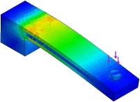
There is one other factor to consider when choosing acceleration. If your robot is going up inclines or through rough terrain, you will need a higher acceleration due to countering gravity. If say your robot was going straight up a wall, you would require an additional 9.81 m/s^2 (32 ft/s^2) acceleration to counteract. A typical 20 degree incline (as shown) would require 11 ft/s^2.
How do you calculate how much additional acceleration you would need for a specific incline?
You must add this acceleration to what you already require for movement on flat terrain.
Robot Motor Factor The robot motor factor (RMF) is something I made up. It is simply a way I devised to make your life simpler so you can do a quick calculation to optimize your robot. Basically I combined and simplified all the equations above into one big equation to help you choose the motor that best suits your robot.
1) To use this equation, look up a set of motors you think will work for your robot and write down the torque and rps (rotations per second) for each.
2) Then multiply the two numbers together for each. This will be your robot motor factor.
3) Next, estimate the weight of your robot. Basically add up the weight of all the parts.
4) Lastly, choose your desired velocity and acceleration.
5) Compare both sides of the equation
Example. Suppose you found three motors: Motor A: 2 lb ft, 1rps => RMF = 2 lb ft rps Motor B: 2.5 lb ft, 2rps => RMF = 5 lb ft rps Motor C: 2 lb ft, 4rps => RMF = 8 lb ft rps
Now suppose you want a velocity of 3 ft/s, an acceleration of 2 ft/s^2, and you estimate your robot weight to be 5 lbs.
so RMF >= 5 lbs * 2 ft/s^2 * 3 ft/s / (2 * pi)
therefore RMF >= 4.77 lb * ft * rps
So this means you need a motor with an RMF greater or equal to 4.77. Looking at your list, Motor B and C both will work. However Motor C is probably overkill, so it's just a waste of money. Therefore you would use Motor B. Just note that if none of the motors would work, you would have to either reduce weight, or go slower, or find another motor.
You are finished! You use motor B, with a wheel diameter of 5.73", and never again will your robot fail at plowing over the neighborhood cat.
Although the above equations are intended for robot wheels, they will also work for any other robot part. If you were say designing a robot arm, instead of using diameter use robot arm length. Then you can calculate how fast the arm will move with a certain weight being carried, for example.
Robot Motor Factor, Efficiency The RMF you calculated is only for a 100% efficient system. But in reality this never happens. Gearing and friction and many other factors cause inefficiency. I wont go into how to calculate efficiency, but there are general rules that would get you really close. If you have external (not inside the motor) gearing, reduce your efficiency by ~15%. If you are using treads like on a tank robot, reduce by another ~30%. If your robot operates on rough high friction terrain, reduce another ~10%. For example, a tank robot on rough terrain would have an efficiency of 100% - 30% - 10% = 60% or 0.6.
Momentum Ever notice how heavier things are harder to push than lighter things? This is because of momentum. Knowing your robot's momentum is very important if you want high acceleration for your robot. If your robot is heavy, it will take forever for a weak motor to get it to go fast. How do you determine the momentum of your robot? Just multiply the mass times the velocity. Lower momentum is better for mobility and higher energy efficiency. Higher momentum is better for beating up other robots . . . and people.
Introduction to Mechanical Engineering Theory, Statics Want to optimize your robot parameters mathematically? Want to verify that an expensive motor you are about to purchase has enough torque? This is a math tutorial for robot chassis construction. This tutorial is useful if you would like to mathematically either prove your robot will work, or optimize it so that it would work better. Better yet, I have one of those degree thingies in Mechanical Engineering so this tutorial should be extra useful . . .
My approach will be talking about the most common calculation uses of mechanical forces for robots. I will offer specific application examples, the theory, equations, and some pretty graphs to help you understand.
Theory: Statics Statics is concerned about how a mechanical system would act if everything is perfectly motionless and rigid. It is the most fundamental of all calculations, and mathematically is no more complicated then highschool algebra. All you need to understand is how to build an equation from the mechanical parts you use.
Remember in elementary you learned (or should have learned) that for every force there is an equal and opposite force? For example, if I were to stand straight, then push you forcefully, I would end up forcefully pushing myself back at an equal amount. If you push a wall, the wall is pushing you back. Why is this important? Easy. If an object weighs 10 pounds, your actuator needs to be able to lift at least 10 pounds. This sounds numbingly simple, right? Now suppose you add in friction of joints, efficiency rates, multiple actuators, and unevenly distributed weight across an oddly shaped object. Obviously the problem can balloon to something quite complex. This is what I will talk about, all directly relating to robotics and in simplified form.
Moment Arms Moment arms will probably be the most useful for you. The basic equation is moment equals force times the distance of the beam the force is being applied perpendicularly at.
Moment = Force * distance
Here is the first example. What you see is an object of some length. It is fixed rigidly at one end. And the other has some force being applied to it. This force can be something hanging on it, something pushing it, a hammer hitting it, a gear moving it, gravity/weight, etc. Does not really matter.
All you do is measure the distance and multiply that by the force that is being applied. You should always know the expected force being applied to your robot, or you are taking a risk of buying an actuator that is too weak or too big and strong. If the robot is lifting a beer can, know the weight of the can. If the robot is climbing, know the estimated weight of the robot. Even rudimentary calculations can help you better understand the force requirements of your robot.
Now suppose your robot is lifting a beer with an arm. A moment about the shoulder is being created by both the weight of the can, but also the weight of the robot arm itself. How do you calculate this? You would add the moments created by each together.
Notice that for the arm length we only use half the value. Why? Because weight is distributed throughout the entire arm. Theoretically all you are doing is adding up all of the force across the arm, and applying it to the center of mass of the robot arm. The center of mass is the exact point where an object can be perfectly balanced. I estimated the center of mass to be the midpoint (1/2 length) of your robot arm. However it may not be. You can easily find the center of mass of any object by balancing it on your finger and then measuring that distance with a ruler.
Now suppose you have calculated the moment. What do you do with this number? This is actually the torque being applied. So when you look for a motor to power the shoulder of your robot, just reference this calculated value as your minimum required torque.
The concept of the moment arm can be applied for many different situations. Sometimes the moment arm can be hidden, so here are a few more examples:
Pulleys Calculating pulley forces is very simple. A pulley is a simple moment arm. The force being applied on the rope multiplied by the pulley radius is the torque being applied. But now notice that there are two forces countering each other. This is like two opposite moments, so you would subtract them. Remember, don't be confused by the device itself. Even if the pulley were square, the calculation would still be exactly the same. Can you see the moment arm in this example?
You should also note Force C, the force required to hold the pulley up. Force C is always Force_A + Force_B + pulley_weight.
Crowbar - Mechanical Advantage Moment Balancing Another example of a moment would be a crow bar. What you have is a beam, a pivot point in the center, and a weight on each end. Now suppose you have two exact same weights. Now move one of those weights real close to the pivot point. What will happen? The weight that did not move would go down. Although the force remained the same, the distance decreased, therefore resulting in a smaller moment.
Although this example looks very different from the rest, it is actually exactly the same.
Both sides of the crowbar create a moment about the pivot point (the triangle tip). So your equation is this:
Moment Side A = Moment Side B
Force_A * Length_2 = Force_B * Length_1
Now if you knew any three variables out of the four, you can use simple algebra to calculate the fourth one.
For example, suppose this was a see-saw at a childrens' playground. Now you have a 40 pound child sitting on one end, and you plan to catapult him into the next playground. Now this child is sitting exactly 4 feet from the pivot point. Your plan is to jump on it with your weight of 200 pounds. What is the closest distance to the pivot point you can stand on the see-saw and still lift the child into the air?
filling in the equation: 40 lbs * 4 ft = 200 lbs * distance
solving: 40 * 4 / 200 = distance = .8 feet
Safety Factor If you are unsure of various perhaps uncalculatable factors, always add what is called a factor of safety. For example, suppose you guess a beer can weighs between 1 to 2 pounds. A factor of safety would say, 'design the system to handle 2.5 pounds, just in case.'
So what should your factor be? Guess. I would recommend 1.2, but its really up to you. What does this number mean? Suppose your calculations say you need a motor rated at least 100Nm, then multiple that by 1.2 to get 120Nm as your minimum motor force. The factor of safety is not an exact science, obviously. If you expect to have high fatigue from shock or overuse, high friction, or bending, make the factor of safety higher.
So why not make my safety factor really high? Well, you can, but motors with higher torques are also more expensive. Thicker robot materials can cost you more too. So why not a small safety factor? Well, if friction is much higher in your robot than you expected, your robot just won't work very well.
There is a more scientific method to the safety factor, called statistical analysis. This involves building then actually testing your robot part under various circumstances until it breaks. Then statistically (through a histogram) you can determine the optimal properties so it will NEVER break. However this involves building and breaking a part many times - too much effort for a single robot. This method is common for car and cell phone manufacturers. Did you know they statistically determine how many times you can drop a cell phone at any particular angle to make it user proof?
Friction Calculating friction is often a black art. There are many situations which are hard to factor in such as surface tension, humidity, etc. But there are several sure ways to find a reasonable value to help you build your robot. The first thing you should look at is what is called the coefficient of friction. This is a dimensionless property which can be looked up for any two materials. What does this number mean? Well suppose you are standing on ice with rubber shoes and you want to calculate the pushing force required to slide across the ice.
force of friction = weight * u.rubber-ice
Just multiple the force being applied perpendicular to the contacting materials (your weight) and multiply that by the coefficient of friction of ice against rubber. This would be the force required to counter friction to slide across the ice.
Understanding friction is also useful when designing robot pincers. If the friction is miscalculated, your robot victims would be able to escape! Now we cant have that . . . So here is how you do it. A robot pincer squeezes from both sides. So this is your force. The typical human however wants to fall down out of your robot pincers by gravity.
Now all you need to do is squeeze hard enough so that the force of friction is greater than the force of gravity.
You probably won't find a reliable coefficient of friction for robot pincers rubbing up against a human neck, but using higher friction pincer material will help.
Actually, finding the coefficient of friction can be a little more complicated. There are actually two coeffiecients. It turns out that friction is related to the rubbing velocity of the materials. Ever notice how it is easier to push a heavy object across the ground after it is already moving?
The static coefficient of friction is when the materials are stationary. The kinetic coefficient of friction is when the materials are already in motion against each other. What makes it a black art is that there is never any exact clear boundary between the two values.
Here is a quick coefficient of friction lookup reference of some common materials you may use:
This robot tutorial should help you with the mechanical aspect of building your very first robot. You should have already read my build your first robot tutorial before moving on to this tutorial.
Design When I first started building my first robot, someone much more experienced than me once said paraphrased, "if you build a mechanically crappy robot with expert programming and control, you will only get a crappy robot; build a mechanically professional robot with crappy programming and control, you will still get a well built robot." Its very good advice which I still use today.
Planning. Would you say someone who plans his future will have a better future? YES! I cannot emphasize any more for you to design your robot out on paper (or computer) first. This means plan out everything, such as what material to build your robot out of<, where to put every screw, how you will attach your sensors - EVERYTHING. You will save money and time, and will have a better constructed robot too. To do this, you should draw all your parts out to dimension, mark your holes, and understand how all your parts connect.
Use fewer and simpler parts! You will probably quickly realize that the fewer parts your robot has, and the simpler they are, the less you will have to design, make, and pay for. As you design your parts, always consider how you will actually manufacture these parts. Don't use unneccessary or over complicated features, or designs you do not have the tools to make or are really hard to make. Fewer and simpler parts also mean a smaller chance for mistakes in your design. K.I.S.S.
Use off-the-shelf parts. When you purchase a part, it costs money. However there is a good chance that the off-the-shelf part is better than anything you can design and build yourself. Off-the-shelf parts are already well engineered, designed, and tested. This means there is less likely to go wrong on your robot, and less time and effort you need to spend to finish it. How much is your time worth? No point in spending 20 hours making a ghetto circuit when you could buy a high quality one for just $20. Ask yourself if the price of a part is greater or less than your willingness and ability to make the part yourself.
Do not use more than 2 or 3 different screw types. There was a robot I once had to work on that another engineer built. He used a different screw type for every part! I had to use like 10 different unlabeled hex wrenches and 2 different screwdrivers to assembly/dissasemble it. Even worse, he had to purchase 10+ different boxes of screws! If you can make your entire robot out of only the very common 4-40 screws, you are on the right track.
Frame The frame of your robot is the basic structure to which you attach everything else. It is probably the largest part of your robot, so make sure it is made of a light weight rigid material such as aluminum or HDPE. I recommend reading those tutorials as well.
Materials If you are like how I was my first 3 years of building robots, you are probably super cheap and incredibly poor. Robot parts are expensive. Don't even pretend you can make a robot out of parts just lying around your house. Check out my tutorial on funding your robot. To summarize, expect to spend about $10-$50 per robot motor, about $20 on frame material, wheels about $8, and about $10 on miscellaneous nuts and bolts. You can try to search garbage bins and other old stuff for this, but you may or not be lucky. You might be able to find a few reasonable good motors, but it might be much harder to find two of the same motors. Just don't build a crappy robot because cereal box cordboard is the only material you can find!
Mounting When a beginner asks 'how do I attach my robot part?' what they are really asking is 'what is the best way to mount this part?'. Every part on a robot has a different method of mounting. This is due to obvious constraints such as placement, weight, size, function, etc. So I will go over each of the parts you may want to mount and tell you one or two of the best ways to do this.
Wheel Basics Wheel diameter. When buying (or making) your wheels you want to put your motor into consideration. For a start, there is torque and velocity. Large diameter wheels give your robot low torque but high velocity. So if you already have a very strong motor, then you can use wheels with larger diameters. Servo's already have good torque, so you should use larger diameter wheels. But if your motor is weak (such as if it does not have any gearing), you want to use a much smaller diameter wheel. This will make your robot slower, but at least it has enough torque to go up a hill! Another dumb mistake someone can make is buying a wheel that has a diameter close to or less than the motor diameter. For example, if you have a 1" diameter motor, and a 1.5" diameter wheel, you have a .25" ground clearance ( (1.5"-1")/2=.25" ). How high is the tallest object you want to go over?
Wheel texture. The texture of your wheel is very terrain dependent. A common mistake for beginners is to ignore the texture of the wheel. If your wheel is too smooth then it will not have much friction. This is a serious issue with omni-wheels. An all plastic omni-wheel works poorly compared to an omni-wheel that uses rubber for the side wheels. Overly smooth robot wheels would likely skid while accelerating and braking. However a wheel that is really rough, such as a foam wheel, has higher friction with the ground leading to innefficiency. You also need to consider wear and tear on the wheel.
Wheel width. You do not want it too wide as it causes increased resistance to rotating the wheel on a surface. I once used a 1" foam wheel on a concrete surface and it was very poor at rotating.
Wheel center hole diameter. This is where you would actually mount the output motor shaft to your motor. So you must know the length and diameter of your motor output shaft so that you may put this shaft into the hole of your motor.
Mounting Your Robot Wheel Techniques Jamming. Lets start with a basic wheel attached to a basic motor. If the wheel does not have a center hole, just drill one out slightly smaller than the diameter of the shaft of your motor. Make sure the hole is perfectly centered!!!! Then you can fill the hole with a little superglue, and finally press fit (jam, if you will) the motor shaft into the wheel. Perhaps use a little more superglue around the edges.
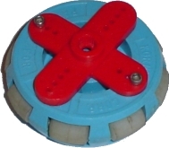
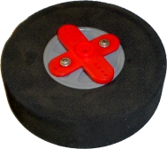
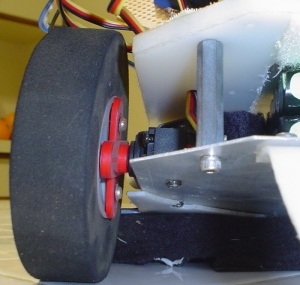
Servo Wheel Mounting. Mounting a wheel onto a servo is fairly easy, and only requires a little drilling. When you purchase a servo, you also get a bunch of other little goodies with it. One of the items is called a servo horn. This is usually a black/red circular, X shaped, or I shaped plastic piece that attaches to the output shaft of the servo. So what you do is attach the wheel to this servo horn, then just screw the servo horn as designed into the servo. In the images below, I drilled two holes into my wheel, 2 holes into the servo horn (the red X thing), and screwed 2 screws into it to hold them together. Then I just attached the servo horn to my servo output shaft with a 3rd screw.
This servo wheel mounting method, with slight modification, can work for other motors too. Just make your own custom 'servo horn' with a custom hole designed to fit your motor output shaft.
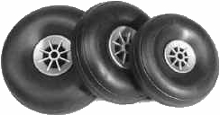
Purchasing Wheels The best robot wheels are actually hobby RC aircraft wheels. Strange, huh? Anyway, there is a huge variety of them online for you to choose from. Just go to any RC hobby website. For example, I have bought several wheels from this online RC hobby store.
Motors There are huge varieties in motors. But for your robot I will assume you are using a basic DC motor. Make sure you get a motor which already has a gear box attached, as it makes your robot much better controlled, more efficient, and stronger. Designing your own gearing and/or chain systems can and will cause you headaches. My first attempt at it was a miserable failure . . . I recommend against trying it.
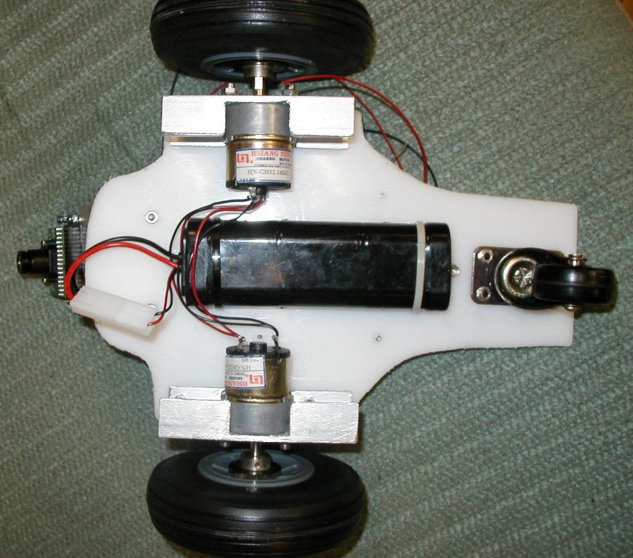
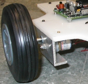
Motor Mounting To mount any type of motor to your chassis you will need to use an L shaped bracket. For a DC motor, all you need to do is take a sheet of aluminum, drill two holes in two of the corners, drill two more holes on the other half to match the motor screw holes, then bend the entire piece in a 90 degree angle. This particular image I had found a U shaped piece of aluminum in some bin, I cut it to size, and just drilled the appropriate holes to attach it to my white HDPE chassis.
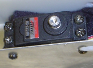
Servo Mounting To mount your servo to your chassis, once again you will use the little baggie of goodies that came with the servo. You should have two black cube looking things with holes in it. There will be three holes in front and a single hole on the bottom. Your servo should also have four mounting holes, two on each side. Using screws, attach the front of the black things to each side of the servo. As shown in the image below, then attach your robot base with two more screws to the bottom hole of the black thingies. This particular robot used a thin reinforced sheet of aluminum as the base with two drilled holes for the mounting screws.
And the completed mounted servo and wheel configuration . . .
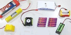
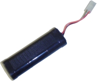
Mounting Robot Batteries Mounting your batteries is very simple. As long as you are using an RC battery pack (such as NiCad or NiMH, you can simply mount your batteries to your robot using strips of velcro. This is the velcro that has a sticky tape side and a velcro side. The advantage to this mounting method is that you can easily swap out your batteries for freshly charged ones - great if you are in a robot competition. You can also group multiple batteries together using zip ties. This is an example of a velcro strip taped to a NiCad battery pack:
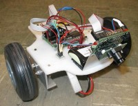
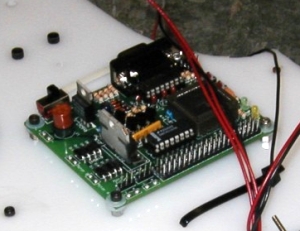
Electronics Mounting your electronics to your robot can potentially be tricky. If you're lucky, your microcontroller has holes for screws or something other method of mounting. For this Cerebellum microcontroller (pictured below) I drilled holes into my HDPE robot base, then screwed short metal spacers into the HDPE. Then all I had to do is put my screws through the Cerebellum screw holes and screw them into the spacers.
Things to keep in mind when mounting your electronics . . . Keep your electronics high up on your robot. It probably weighs little, so you want the heavier items using the space closer to the ground. You want to keep it out of splashing dirt too. Also keep in mind you probably want certain sensors and other sensitive electronics to stay away from your motors as electronic noise could cause interference. Lastly, plan out your wiring on your chassis - have routing holes drilled through your chassis beforehand, for example.
Mounting Sensors Mounting sensors is very much a case-by-case basis. What makes mounting sensors difficult is that you are very limited on where you can place them onto your robot. They must be away from noisy motors, and probably at the front/sides of your robot. You must also keep them protected so that collisions and dirt wont damage your sensors too. If your robot is a line follower, you have to keep your sensors at an exact distance from the ground or risk bad data - even when the ground is uneven! If you are lucky, your sensor has screw holes in just the right place at just the right angle. But in my experience this is very unlikely. Unfortunately I have not yet mastered the art of mounting sensors (because of the huge variety of them), but I can go over a few tricks. So you must get creative, build a mount, use a little glue . . . you get the picture.
Here (click to enlarge) you see a homemade aluminum mount for a sonar transducer and another mount on a servo for two Sharp IR Rangefinders. The sonar mount is aluminum bent at 90 degrees with a few screw holes drilled into it, and plastic spacers to prevent any shorting of the circuit board with the aluminum. The IR Rangefinder mount is aluminum with double sided sticky tape holding the sensors onto the aluminum plate.
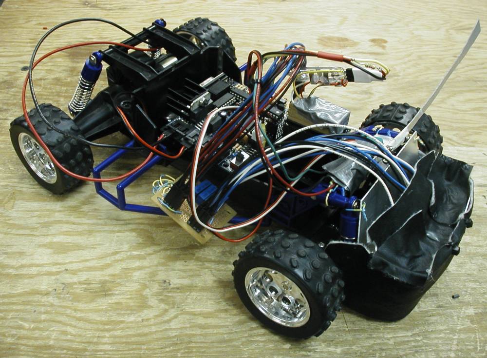
Hacking RC Car Frames (the cheating method) Hacking a toy remote controlled car or tank is a great way to get a professionally built robot chassis with much less work. In this image (click to enlarge) I took a $10 car, hacked the motor wires, and attached all my electronics to it. When buying an RC vehicle, understand that you want a high quality motor so I suggest to avoid the cheap $10 toys. Get something nice if you are going to spend any money on your robot. Notice that you do not need a wireless car! Make sure that the car you will purchase uses a servo for it's rack-and-pinion steering, or you will have to place in your own. I placed my own servo into this cars' steering mechanism so it's definitely possible, but it took time/effort and wasn't perfect. The servo is the easiest way to do any steering system because it has position control.
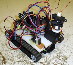
Robot Tank Treads I have never actually built tank treads onto a robot before - mostly because I have been told, and I fully understand, how difficult this task can be. The best way to get treads for your robot is to get a motorized toy tank and hack it into a robot like you would for any RC car. In this robot I ripped off the top part of the tank, drilled screw holes into the plastic, and screwed on a flat sheet of HDPE. From there you can mount whatever you want onto the HDPE - electronics, sensor setups, etc. I also ripped out the guts and used the empty space inside to store my happy little NiMH battery. I built this robot in less than 5 hours (minus programming and testing). It's that easy!
Name: Musa Home: Depok, Jawa Barat, Indonesia About Me: Seorang yg sederhana, moderat, individu serta suka dedikasi dan komitmen dalam semua aspek hidup. Dalam pandanganku sendiri sebagai seorang stabil, bertanggung jawab, percaya diri dan orang penuh kasih yang mempunyai niat baik. Kenangan dari segalanya langkahku merupakan pengalaman berharga dimasa mendatang. Petualanganku dimulai dari pulau “Celebes” yang lebih dikenal dengan Sulawesi. Tepatnya di daerah Gorontalo tempat kelahiran dan masa-masa kecilku bermain dan tumbuh.
Minat yang berkisar akademis terutama hardware system, petualangan. Mengunjungi suatu tempat dan hidup bebas dari “penjajahan” kesenangan penuh kasih.
Bagaimanapun, seorang Purnawarman Musa masih merasakan bahwa aku bukanlah seorang yang sempurna.